Mornsun partners with ON Semiconductor to put IGBT drive circuit at the heart of solar inverter design
To support developers of solar inverters, ON Semiconductor and Mornsun have partnered the their QA151 DC-DC converter with ON Semiconductor’s driver IC and transistors in an Insulated Gate Bipolar Transistors (IGBT) gate driver demo board.
To meet the increasing demand for renewable energy around the world, the two companies have collaborated on a development board to support design engineers evaluate the effectiveness of an IGBT-based power system.
The primary focus of commercially available alternative energy technology today is solar photovoltaic (PV) power generation, which harnesses the energy of the sun and converts it into usable electricity.

Figure 1: A typical solar PV power generation system
Figure 1 shows a typical solar PV power generation system. Solar PV arrays generate electricity from sunlight, which is converted from direct current (DC) to alternating current (AC) using an inverter. This AC power than is fed into the grid for home or business use or, when not directly required, is used to charge batteries via a bi-directional energy storage inverter, thus making power available not just during daylight hours
In centralized or distributed electricity generation system networks, there is always a DC-AC inverter at the heart of the solar PV system. The inverter makes use of IGBT full-bridge circuits to convert the DC energy into a useable AC waveform.

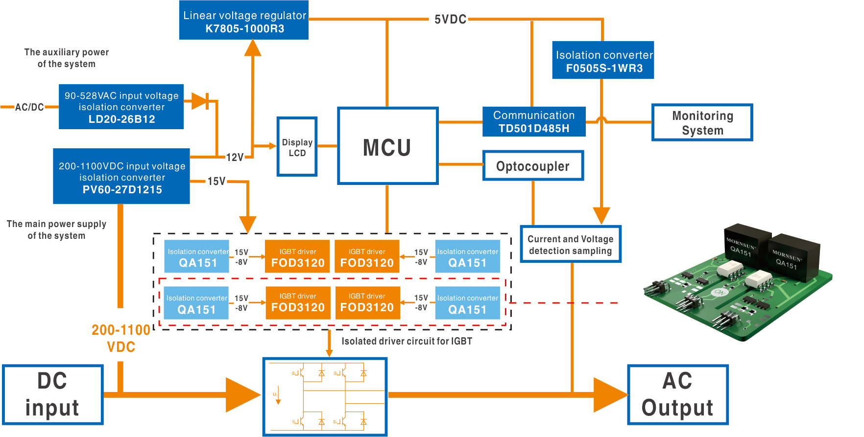
Figure 2: Block diagram of a typical distributed inverter
Figure 2 is an example of a typical inverter system. A wide input DC-DC converter (Mornsun’s PV60-27D1215) generates stable 12V and 15V rails for the control electronics. The DC bus feeding the converter can come from multiple PV panels with input voltages up to 1100V DC. The DC-DC converters require isolation voltages in excess of 4000V AC in order to maintain appropriate safety levels and to maintain the safe and reliable operation of the control system.
The IGBT drive board
The IGBT drive circuit is used to isolate, transmit, and amplify control signals which drive the main power transistors. There are specific requirements for a safe and reliable IGBT driver which system design engineers should consider:
IGBT operating characteristics dictate that the junction capacitor (Cge) needs to be charged/discharged when the IGBT is turned on or off. Therefore, the gate drive DC/DC power supply needs to have asymmetrical positive and negative output voltages, and meet the requirements of transient charge and discharge current of the junction capacitance, to ensure that the IGBT can be turned on and off quickly.
When the high DC voltage is inverted to an AC voltage, the IGBT generates a high frequency and high amplitude interference signals during fast turn-on and turn-off. The drive circuit needs to have high transient immunity to cope with these disturbances, a high isolation voltage, and low isolation capacitance, to ensure reliable operation and avoid common-mode interference signal conduction to the system control board.
The high current, high voltage operating environment of the IGBT causes large temperature rises inside the system during inversion. As a result, the gate drive DC/DC power supply needs to have a high operating temperature range.
ON Semiconductor has developed a gate drive demonstration board for system designers developing high power solar inverters featuring the Mornsun QA151 combined DC-DC converter and gate drive.
Development support


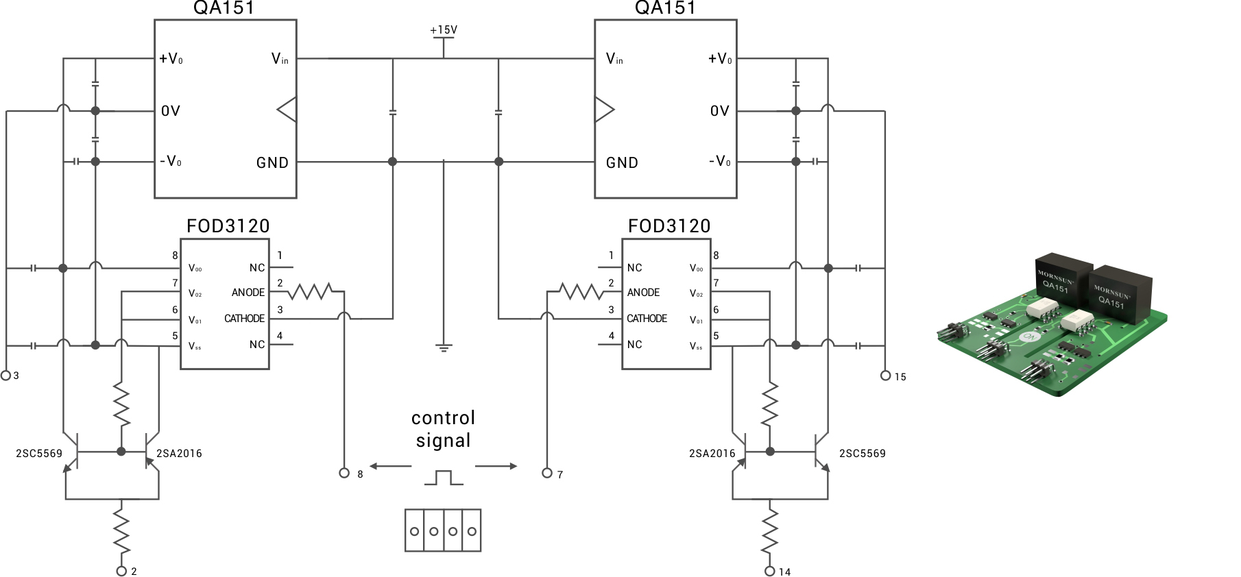
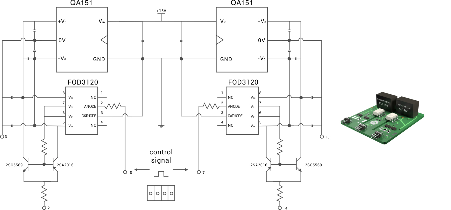
Figure 3: Circuit diagram of the ON Semiconductor driver demo board, with Mornsun’s QA151 power module.
The Mornsun QA151 is a DC-DC converter specifically designed for IGBT drivers. It has 2 asymmetric outputs (+15/-8.0V DC) with very low input to output capacitance, making it the ideal DC-DC Converter to power ON Semiconductor’s FOD3120SD driver IC and 2SC5569 and 2SA2016 transistors.
The QA151 also has a wide operating temperature range from -40 to +105℃ and is supplied in a compact, internally-potted 7-pin SIP case (19.5 x 9.8 x 12.5mm, saving valuable board real estate on space-constrained solar inverter designs.).
A high-quality isolation transformer provides up to 3000Vac. The QA151’s isolation capacitance is only 6pF, ensuring excellent interference immunity for the demo board. Additionally, with an output current up to 120mA and the ability to drive 200uF capacitive loads, meets the general power requirements for power IGBT bridge circuits.


